


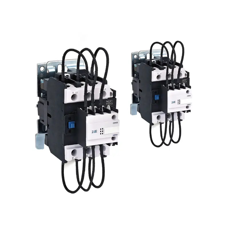
A capacitor switching contactor is a specialized electrical device designed to safely connect and disconnect capacitor banks in power factor correction systems. Unlike standard contactors, these units include pre-charge auxiliary contacts and damping resistors that absorb high inrush currents, preventing contact welding and voltage transients that can damage sensitive equipment.
Power factor correction is essential for avoiding utility fees and improving efficiency. But closing a switch onto a discharged capacitor creates a momentary short circuit with current up to ten times nominal levels. That harsh electrical reality is why engineers specify a capacitor switching contactor rather than a standard power contactor. Here is how the internal design makes the difference and what to look for when selecting one.
Why Standard Contactors Fail in Capacitor Duty
Standard contactors bounce when closing on a capacitor bank. During this bounce, inrush current can spike to 100 times the steady-state rating, vaporizing contact material. This eventually causes welding or severe pitting.
A capacitor switching contactor prevents this with a staggered closing sequence. Early-make auxiliary contacts with damping resistors engage first, slowing the voltage rise. Milliseconds later, the main contacts close into a partially charged circuit, reducing inrush current to a safe level.
Key Advantages in Power Distribution Panels
The immediate benefit of using a Capacitor Switching Contactor is extended equipment lifespan, but the operational advantages extend further into the electrical infrastructure:
●Prevention of Voltage Transients: The controlled switching action suppresses the oscillatory transients that otherwise travel back into the busbar system. This protects nearby variable frequency drives and PLC logic controllers from spurious trips or damage.
●Reduced Maintenance Downtime: Contact welding is the primary failure mode for contactors switching capacitive loads. By mitigating this risk, these devices keep automatic power factor correction banks online with fewer emergency service calls.
●Compliance with Harmonic-Heavy Environments: Many modern capacitor banks operate in networks with high harmonic distortion. These contactors are engineered to handle the thermal stress associated with harmonic currents without derating as severely as general-purpose AC-1 contactors.
Common Application Environments
Understanding where this component belongs helps buyers avoid over-specifying or under-protecting their panels.
Automatic Power Factor Correction (APFC) Panels
This is the primary application. A regulator monitors lagging power factor and cycles capacitor steps on and off multiple times per hour. This frequent switching demands the mechanical endurance of an AC-6b rated contactor.
Fixed Capacitor Banks for Motors
Large induction motors often use fixed capacitance at the terminals to offset no-load reactive power. A capacitor switching contactor brings this online simultaneously with the motor starter, preventing current spikes that would otherwise trip the overload relay.
Wind and Solar Farm Auxiliary Circuits
Renewable energy substations need reactive power support at the low-voltage level. These contactors offer a compact, reliable way to switch smaller capacitance steps, fine-tuning output before it reaches the main transformer.
Selecting the Right Size and Rating
Buyers should look beyond just the kilovolt-ampere reactive (kVAr) rating on the label. Here are the practical considerations that ensure the device meets the site’s actual demand:
●Peak Inrush Current Capability: The datasheet will list a maximum peak current rating (often noted as Î). For networks with a high prospective short-circuit current or when switching banks that have been recently discharged, this parameter is more important than the AC-6b thermal current.
●Discharge Time Compliance: A Capacitor Switching Contactor assumes the capacitor has been sufficiently discharged before the next closing operation. If the load cycle requires re-closing within less than 50 seconds (depending on the size of the discharge resistors), the contactor will be subjected to a higher duty cycle. Ensure the panel includes proper discharge bleed resistors to protect the contactor.
●Coil Voltage and Control Logic: Many of these contactors feature a high pull-in VA requirement on the coil. Ensure the control transformer or power supply in the panel can handle the momentary inrush without sagging below the dropout voltage.
Installation Notes for Panel Builders
Physical layout inside the enclosure directly impacts device longevity. Keep these contactors away from heat sources like line reactors or soft starters, as excess ambient temperature degrades coil insulation and shortens damping resistor life.
Wiring also matters. Minimize the loop area between the contactor load side and capacitor fuses. A larger loop adds inductance, worsening transient overvoltage despite the contactor’s internal protection. Keep leads short and twisted for best results.
Summarize
For facility managers, the choice comes down to reliability versus upfront cost. While a dedicated switching contactor costs more than a standard AC-1 unit, avoiding just one instance of contact welding and production downtime easily covers the difference. It is engineered to manage the extreme physics of charging a capacitor, making it the industry standard for stable reactive power control.
Post time: Apr-13-2026